
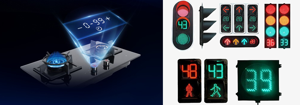
The electronic counter can be used for counting number/length/batch, position control of balers controlled by variable frequency motor, and measuring height, position and angle. Handheld digital counter features 6 digit display, 4 kinds of up/down input modes, a DC 12V/24V external power supply, can preset count value or length, and simultaneously display the total count, counting length and batch value in real-time.
Features
- Digital counter accuracy: 0.01%, minimum resolution: 0.0001.
- Input/output signals photoelectric isolated, anti-interference ability.
- Input: 4 kinds of input modes, a variety of input signals, various waveform pulses, grating, proximity sensors, photoelectric sensors, contact switches, encoders, etc. (NPN, PNP).
- Output: 8 kinds of output modes to select, up to 3 segments of control output, suitable for various control requirements.
- 6 digit display, has external power supply DC 12V/24V/30mA, especially for sensor.
- Standard RS232 or RS485 MODBUS RTU communication, can be directly connected with computers, PLC or other equipment.
Applications
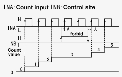
In the digital system, the counter mainly counts the number of pulses to realize the functions of measurement, counting and control, and also has the function of frequency division. Digital counters are widely used in various fields, including industrial production, digital systems, traffic signal control, paper cutter positioning and elevator positioning and speed regulation.
| Mode | SISCO-DIGC-FH6 |
| Weight | 300g |
| Accuracy | 0.01% |
| Power supply | AC 90-260V, or AC/DC 12-30V/DC 24V, power dissipation≤5VA |
| Input signal | Pulse signal, square wave, sine wave, 5V≤H≤30V, 0≤L≤2V, rising edge trigger, frequency: 0.01~9KHz (square wave) |
| Counting rate | ≤5000 CPS (switching input, software selectable), ≤2000Hz (encoder input) |
| Display counting range | -199999~999999 |
| Ratio setting range | 0.00001~99999.9 |
| Input impedance | ≥10KΩ |
| Relay output method | R, N, C, F, H, L (count), upper and lower limits alarm, capacity AC 250V/3A, DC 30V/3A COSΦ=1 |
| Transmission output | 4-20mA, 0-10V, etc. (range can be set) |
| Insulation resistance | ≥100MΩ (between DC 500V power terminal and external terminal) |
| Dielectric strength | AC 1500V 1min (between power terminal and external terminal) |
| Environment | Ambient temperature: 0~50°C, relative humidity: 35~85%RH |
| External power supply | DC 12V±5%, 50mA max / DC 24V±5%, 30mA max |
| Protection class | IP65 |
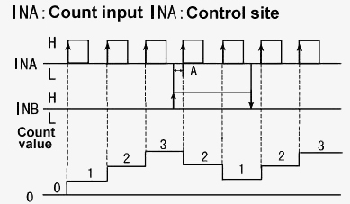
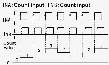
Digital Counter Up/Down Input Modes
Mode A: Up (addition)
INA counts up. INB is GATE function. When INB is high level (or shorted with +12V), INA input is forbidden.
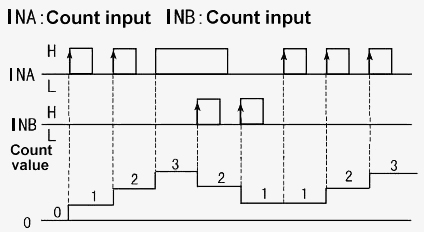
Mode B: Up/down (addition or subtraction)
INA counts up. INB is a count-down control function. When INB is high level, INA turns count-up into count-down.
Mode C: Up/down (addition and subtraction)
INA counts up, INB counts down.
Mode D: Up/down (for encoder)
INA signal leads INB signal (count-up). INA signal lags INB signal (count-down). It is often used for encoder or grating input.
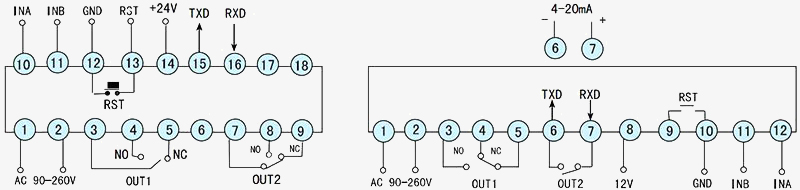
Wiring diagram
Q1: What is a digital counter?
A1: Counting is one of the simplest and most basic operations. In digital logic and computing, a counter is the logic circuit that implements this operation. In digital systems, a counter mainly counts the number of pulses for measurement, counting, control, and other functions. It also has a frequency division function. A digital counter consists of a basic counting unit and some control gates. The counting unit consists of a series of various flip-flops with the function of storing information. These flip-flops include RS flip-flops, T flip-flops, D flip-flops and JK flip-flops. Counters are widely used in digital systems. For example, in the controller of an electronic computer, the next instruction is taken out sequentially by counting the instruction address. The operation unit records the number of additions and subtractions when multiplication and division operations are performed. A counter can be used to indicate the operating status of a product. In general, it is mainly used to indicate how many copies of the product have been folded and sorted. Its main indicator lies in the number of bits of the counter, commonly 3 and 4 bits. Obviously, a 3-digit counter can display up to 999 and a 4-digit counter can display up to 9999.
Q2: How to choose a digital counter?
A2: Choosing a digital counter involves considering several factors to ensure it meets your specific needs and requirements. Here are some key considerations to help you make an informed decision:
- The choice of the built-in crystal oscillator.
- The resolution of the digital counter.
- Large screen touch design.
- The counter has more measurement functions.
- Internal crystal oscillator calibration function.
- The communication interface of the counter should be as many as possible.
- Wide measuring range
Q3: What are the Types of Counters?
A3: Counters are electronic devices used to count occurrences of input signals or events. They come in various types, each designed for specific counting applications. Here are some common types of counters:
- According to whether the flip-flops in the counter are flipped at the same time, the counter can be divided into two types: synchronous counter and asynchronous counter.
- According to the increase and decrease of numbers in the counting process, the counters can be divided into addition counters, subtraction counters, and reversible counters. It is an up counter that keeps increasing with the clock signal, and a down counter that keeps decreasing. A counter that can be incremented or decremented is called a reversible counter.
The most commonly used is the first one because it allows people to know at a glance what triggering method this counter is so that designers can design circuits.
Tips: What are the components of a digital counter?
- A, B input channels
The function of the input channel is amplifying and shaping the measured signal to a standard pulse signal. - Door
The gate is a comparison circuit used for quantizing. It can control whether the counting pulse signal can input the digital counter. - Counting and displaying unit
The counting and display circuit is used to count the pulse signal from the main gate and display the result of the counting in a digital form. For easy reading, the digital counter usually uses a decimal counting circuit. - Time base unit
The time base circuit is mainly composed of a crystal oscillator, a frequency divider, and a frequency multiplier. The time base circuit is mainly used to generate various standard time signals. The timing signal can be single or multinomial. - Control unit
The function of the control circuit is to generate three control signals gating signal, registering signal and zero resetting signal. So that various circuit units of a digital counter can automatically measure in an orderly process according to the sequence of preparation, measurement and display.
Thank you for buying industrial test and measurement equipment on sisco.com, all products sold by sisco and the partner cover a 12 months warranty, effective from the date of receiving the products.
What is covered?
sisco is responsible for providing free spare parts, and free technical support to assist the customer to repair the defective products until the problem is solved.
What is not covered?
- Product purchased from anyone other than a sisco store or a sisco authorized reseller.
- Expendable parts.
- Routine cleaning or normal cosmetic and mechanical wear.
- Damage from misuse, abuse or neglect.
- Damage from use of parts other than sisco approved.
- Damage from use outside the product’s usage or storage parameters.
- Damage from use of parts not sold by sisco.
- Damage from modification or incorporation into other products.
- Damage from repair or replacement of warranted parts by a service provider other than a sisco authorized service provider.
- Damage caused by the application environment not meeting the product usage requirements and the failure to perform preventive maintenance.

Shop on sisco.com for all of your industrial test and measurement equipment & accessories including portable detectors, meters, testers, scales, etc.


