
sisco high voltage megger tester can measure the insulation resistance of large transformers, generators, high-voltage motors and so on. Digital megger can be selected from the test voltages of 100, 250, 500V and 1kV, with the capabilities of testing insulation resistance up to 10 GΩ, high performance and reliable.
Megger resistance tester with special adapter jack
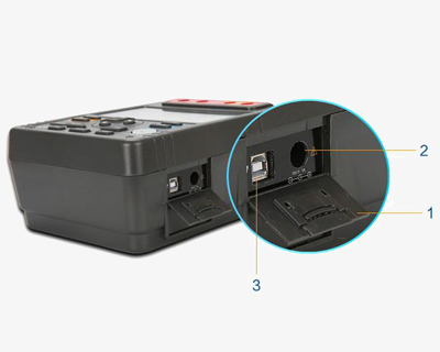
The high voltage megger tester is equipped with a special adapter jack, the instrument must be switched off when the adapter is inserted or unplugged.
- Active door
- Adapter jack button
- USB insertion hole
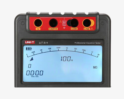
Insulation resistance tester with LCD backlight display
The measurement data is displayed with functional symbols, the readings are clear at a glance and high-definition, and the data can be displayed in a backlight.
Applications
The insulation resistance tester is suitable for measuring the insulation resistance of various electrical equipment and insulating materials such as transformers, motors, cables, switches, electrical appliances, and for maintenance, testing and verification of various electrical equipment.

| Model | SISCO-IRT-UT511 | ||||
| Insulation Resistance (Ω) | Test voltage/accuracy | 100V/250V/500V/1000V | 0% ~ 20% | ||
| Measurement range/accuracy | 100V | 0.1 MΩ ~ 500 MΩ | ±(3%+5) | ||
| 250V | 0.5 MΩ ~ 2 GΩ | ±(3%+5) | |||
| 500V | 1 MΩ ~ 4 GΩ | ±(3%+5) | |||
| 1000V | 2 MΩ ~ 10 GΩ | ±(3%+5) | |||
| Short-circuit current | <2mA | ||||
| DC Voltage (V) | Test range/accuracy | 1000V | ±(2%+3) | ||
| AC Voltage (V) | Test range/accuracy | 30V ~ 750V (50Hz/60Hz) | ±(2%+3) | ||
| Low Resistance (Ω) | Range/accuracy | 0.1 Ω ~ 999.9 Ω | ±(1%+3) | ||
| Features | Display | 9999 counts | |||
| Auto ranging | Yes | ||||
| Auto power off | Yes | ||||
| Low battery indication | Yes | ||||
| Data storage | 18 | ||||
| Comparison measurement | Yes | ||||
| PI | Yes | ||||
| DAR | Yes | ||||
| LCD backlight | Yes | ||||
| Analog bar graph | 30 | ||||
| Over-range warning | Yes | ||||
| High voltage indication | Yes | ||||
| Timing measurement (around 30 min) | Yes | ||||
| General | Power supply | 1.5V battery (LR14) x 8 | |||
| Display size | 123mm x 58mm | ||||
| Operating temperature | 0℃ ~ 40℃ (32℉ ~ 104℉) | ||||
| Storage Temperature | -20℃ ~ 60℃ (-4℉ ~ 140℉) | ||||
| Relative Humidity | ≤85%RH @ 0℃ ~ 40℃ below; ≤90%RH @ -20℃ ~ 60℃ |
||||
| Product weight | 2kg | ||||
| Product size | 202mm x 155mm x 94mm | ||||
| Standard accessories * | 2*single plug test lead with alligator clip (black and green), 1*double plug test lead with alligator clip (red), batteries | ||||
Note: * Batteries are Not Included for air shippment.
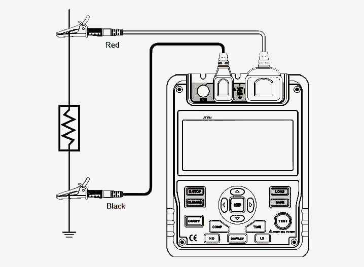
Insulation Resistance Tester Wiring Diagram
Q1: What is a insulation tester?
A1: Insulation tester, also known as megohmmeter or meggers, are widely used to measure cables for generators, motors, power transformers, wiring, appliances and other electrical installations such as control, signal, communication and power ) insulation resistance. They are often used in routine maintenance procedures to indicate changes in the insulation resistance of a motor over months or years. Large changes in insulation resistance may indicate potential failures. Therefore, regular calibration of the megohmmeter is required to ensure that the meter itself has not changed over time.
Q2: What is insulation resistance?
A2: Insulation resistance is the DC resistance of the insulation under the specified conditions, that is, the DC voltage is applied to the dielectric, after a certain period of polarization, the resistance corresponding to the leakage current flowing through the dielectric is called insulation resistance. It is the most basic insulation index of electrical equipment and electrical circuit.
Q3: How to measure insulation resistance?
A3: 1. Connect all the lines according to the method measured by the insulation resistance tester. The connection between the measuring lead and the pipe is more suitable for the use of magnetic joints or clips, and the connection point must be free of rust.
2. The measuring instrument should be a 500V/500MΩ (the error here cannot be greater than 10%) insulation tester. Turn the handle of the megohmmeter to reach the specified speed for 10 seconds. The resistance value indicated by the megohmmeter stably is the insulation resistance value of the insulating joint (flange), which is required to be greater than 10 megohms.
Tips for using a megger insulation resistance tester
- Before the measurement, the power supply of the device under test must be cut off, and the short-circuit discharge to the ground must be performed.
- For equipment that may induce high-voltage electricity, this possibility must be eliminated before measurement can be performed.
- The surface of the object to be measured should be clean to reduce the contact resistance and ensure the correctness of the measurement results.
- Before measurement, check whether the megger is in normal working condition, mainly check its "0" and "∞" points. That is, shake the handle to make the motor reach the rated speed. The insulation resistance tester should point to the "0" position when it is short-circuited, and it should point to the "∞" position when it is open.
- The insulation resistance tester should be placed in a stable and firm place, and away from large external current conductors and external magnetic fields. After the above preparations are done, the measurement can be carried out. When measuring, pay attention to the correct wiring of the megohmmeter, otherwise it will cause unnecessary errors or even mistakes.
Thank you for buying industrial test and measurement equipment on SISCO.com, all products sold by SISCO and the partner cover a 12 months warranty, effective from the date of receiving the products.
What is covered?
SISCO is responsible for providing free spare parts, and free technical support to assist the customer to repair the defective products until the problem is solved.
What is not covered?
- Product purchased from anyone other than a SISCO store or a SISCO authorized reseller.
- Expendable parts.
- Routine cleaning or normal cosmetic and mechanical wear.
- Damage from misuse, abuse or neglect.
- Damage from use of parts other than SISCO approved.
- Damage from use outside the product’s usage or storage parameters.
- Damage from use of parts not sold by SISCO.
- Damage from modification or incorporation into other products.
- Damage from repair or replacement of warranted parts by a service provider other than a SISCO authorized service provider.
- Damage caused by the application environment not meeting the product usage requirements and the failure to perform preventive maintenance.

Shop on sisco.com for all of your industrial test and measurement equipment & accessories including portable detectors, meters, testers, scales, etc.


