
PID temperature controller with multi-channel, PID output control, upper and lower limit control manual switching, power supply AC85V~ 242V (switching power supply), 50/60Hz, support humidity sensor, pressure sensor, load cell, displacement sensor, gas sensor, and other non-standard sensors.
Support a variety of sensors at the same time
- Supports CU50/PT100/K/E/J/T/S/R temperature sensors.
- Support 4-20 mA /0-10mA/ 1-5v/0- 10v/0- 5v current signal.
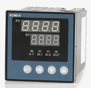
- Double-row four-digit digital tube display, four keys to operate the temperature control meter, display the measured value and the set value at the same time.
Control mode arbitrary switching
- Control mode has upper and lowers limit control, and PID controls two ways to switch at will.
- PID control has a parameter self-tuning function, which can achieve accurate measurement and efficient thermostats for temperature, pressure, flow, etc.
- The PID control has a parameter self-tuning function, which can achieve accurate measurement and efficient constant temperature and pressure control.
Application
Temperature controllers are widely used in various home appliances, such as water dispensers and heaters. The refrigerator uses a temperature controller to adjust the temperature to keep food fresh. The temperature controller can always control the temperature inside the refrigerator within a specific range. When the temperature is higher than the specified range, the thermostat can automatically cool down.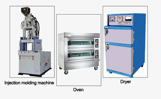
| Model | SISCO-TC-DM |
| Weight | 0.5kg |
| Dimension (Length*High*Depth) * | D1: 160*80*80mm with hole size 152*76mm; D2: 96*96*110mm with hole size 92*92mm; D5: 72*72*110mm with hole size 68*68mm; D7: Rail type 107*88*59mm Note: D2, D5 and D7 apply to dual channels and four channels, and eight channels only has dimension D1. |
| Supply voltage | 85V-240V AC or 24V DC, 50-60Hz |
| Working environment | Temperature: -10~60℃, humidity: ≤90%RH |
| Sampling period | 8 times/second; When set digital filter parameter FILt=0, response time≤0.5s |
| Accuracy | ±0.5%F.S ±1 digit |
| Resolution | ≤0.01℃ |
| Input signal * | I1. Temperature sensor: CU50 (-50.0~150.0℃), PT100 (-199.9~600.0℃), K (-30.0~1300℃), E (-30.0~700.0℃), J (-30.0~900.0℃), T (-30.0~350.0℃), S (-30.0~1600℃) I2. Analog signal: 4-20mA, 0-10mA, 0-5V, 1-5V I3. I1+I2 all signals |
| Control mode | 1. On-off control; 2. PID control Need manually switch to another control mode. |
| Output mode * | O1: Relay output (AC 220V/5A of resistive load or AC 220V/0.3A of inductive load); O2: SSR output (Current ≥15mA, Voltage ≥9V); |
| Alarm mode * | A1 Default mode: 1 alarm output for each channel |
| Alarm | Upper limit, lower limit, upper deviation, lower deviation, in the deviation section, outside the deviation section; Temperature difference on each channel |
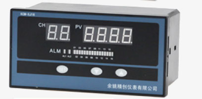
| Multi channel function | Multi channel can realize separate measuring and individual control |
| Additional output mode * | RS: RS485/232 communication (MODBUS-RTU protocol); PT: Printer (TTL232 print out) |
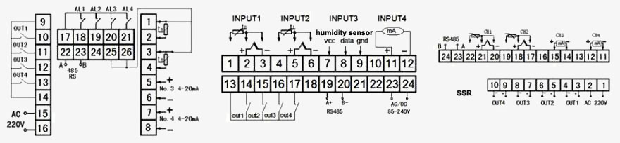
Wiring diagram
1. PID temperature controller wiring diagram (input: I1 temperature sensor)
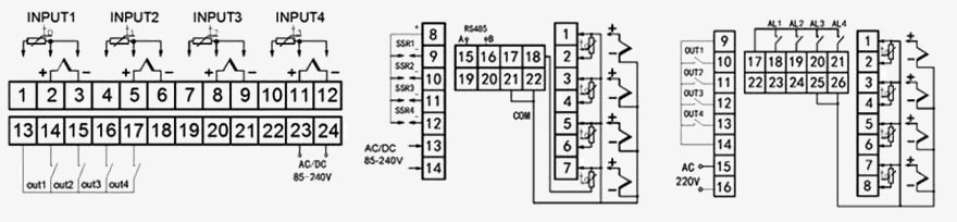
2. PID temperature controller wiring diagram (input: I2 analog signal)
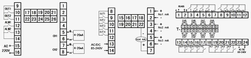
3. PID temperature controller wiring diagram (input: I1+I2 all signals)
Q1: What is a temperature controller?
A1: A thermostat is a series of automatic control elements that generate certain special effects by physical deformation inside the switch according to the temperature change of the working environment, resulting in an on or off action, also called temperature control switch, temperature protector, temperature controller, or thermostat for short. Or through the temperature protector will be temperature to the temperature controller, temperature the controller issues a switch command, so as to control the operation of the equipment to achieve the desired temperature and energy-saving effect.
Q2: What is the working principle of a temperature controller?
A2: Its working principle is to automatically sample and instantly monitor the ambient temperature through the temperature sensor, and the control circuit starts when the ambient temperature is higher than the control setpoint, and the control return difference can be set. If the temperature is still rising, the over-limit alarm function is activated when it rises to the set over-limit alarm temperature point. When the controlled temperature can not
be effectively controlled, in order to prevent the destruction of the equipment can also stop the equipment to continue to run through the function of tripping. It is mainly used in various high and low-voltage switchgear, dry-type transformers, box-type substations, and other related temperature fields used in the electric power sector.
Q3: What is the temperature controller used for?
A3: Digital electronic temperature controller is a precision temperature detection controller, that can be digital quantitative control of temperature, temperature controller is generally used NTC thermal sensor or thermocouple as the temperature detection element.
Tips: What is a relay output?
The relay output is an on/off output, which outputs 0 and 1 through on and off states. although relay output can be directly connected to PLC, it should be noted that the relay is mechanical and has a low speed. So it is not suitable for use at high-speed signals. Also, the relay output is an ON/OFF output, which is not suitable for continuously changing analog signals. In addition, the relay is just a switch. When pull-up or pull-down is required, voltage input cannot be used directly, and pull-up and pull-down resistors are required.

Shop on sisco.com for all of your industrial test and measurement equipment & accessories including portable detectors, meters, testers, scales, etc.


