
Electricity meters, also known as electric meters or watt-hour meters, are devices used to measure electrical energy. They are commonly referred to as energy meters and serve the purpose of measuring various electrical parameters.
When using energy meters, it is important to note that for low voltage (not exceeding 500 volts) and small current (several amperes) situations, the energy meter can be directly connected to the circuit for measurement. However, in cases of high voltage or high current, the energy meter cannot be directly connected to the circuit and requires the use of voltage transformers or current transformers.
Structure and Principles of Energy Meters
Structure of Energy Meters
Energy meters typically consist of three primary components: the current circuit, the voltage circuit, and the dial system.
Current Circuit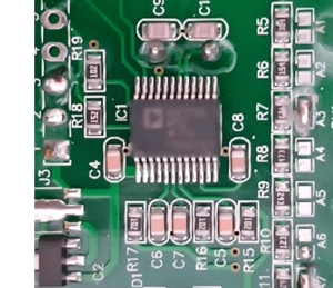
The current circuit is divided into two main parts: the current coil and the magnetic field system.
- Current Coil: The current coil is typically wound with multiple layers of copper wire and is mounted on the iron core of the energy meter. The principle of the current coil's operation involves inducing a magnetic field through the flow of current, which then interacts with the magnetic field system.
- Magnetic Field System: The magnetic field system comprises a magnetic core and magnetic poles. The magnetic core is usually composed of laminated silicon steel sheets to reduce magnetic flux losses. The role of the magnetic poles is to control the distribution of the magnetic field within the current coil.
Voltage Circuit
The voltage circuit also consists of two main components: the voltage coil and the circuit control system.
- Voltage Coil: The voltage coil manages the operation of the energy meter and measures the voltage passing through it. It is constructed using fine copper wire wound around an iron core in the energy meter.
- Circuit Control System: The circuit control system primarily consists of capacitors and resistors. Capacitors play a crucial role in storing energy and filtering noise in the circuit, providing anti-interference properties. Resistors are used for voltage division, current limiting, and precision adjustments.
Dial System
The dial system includes gears, supports, dials, and pointers.
- Gears: Gears are used to transmit the mechanical power of the motor and convert the rotational speed into a numerical display on the dial.
- Supports: Supports hold the motor and gears, ensuring the compact and complete structure of the energy meter.
- Dials and Pointers: Dials and pointers are responsible for displaying the measured values. Energy meters typically have two pointers on the dial, one for displaying current intensity and another for displaying voltage strength. The accuracy of the pointers can be adjusted based on the set measurement range.
Principles of Energy Meters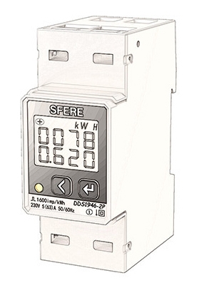
In an energy meter, when current flows through the current coil, a magnetic field is generated within it. This magnetic field interacts with the magnetic flux between the iron core and the magnetic core, causing a torque to occur on a rotating shaft. The voltage coil measures the voltage in the circuit, and through the measurements of current and voltage, the electrical energy in the circuit is calculated.
Traditional energy meters are often mechanical in nature, but modern energy meters frequently incorporate electronic components such as sensors, integrated circuits (ICs), and computer chips. Electronic energy meters offer greater accuracy, reliability, and additional features, including the measurement of power factor and frequency variations in complex circuits.
When an energy meter is connected to the circuit to be measured, alternating current flows through the current coil and voltage coil. These two alternating currents produce alternating magnetic flux in their respective iron cores. The alternating magnetic flux passes through an aluminum disk, inducing eddy currents in the disk. Eddy currents, in turn, experience a force in the magnetic field, causing the aluminum disk to rotate. The torque generated by the force is opposed by a braking torque produced by a permanent magnet. The magnitude of the braking torque is directly proportional to the rotation speed of the aluminum disk. As power consumption increases, the current passing through the current coil also increases, leading to a larger eddy current in the aluminum disk, resulting in a greater rotation force. In other words, the torque is directly proportional to the power consumed. As power consumption increases, the torque increases, causing the aluminum disk to rotate faster. As the aluminum disk rotates, it drives a counter, which indicates the amount of electrical energy consumed. This is the basic operational process of an energy meter. The electric energy meter is an electrical testing tool and has certain dangers. Please use it under professional guidance.


