
Are you looking to ensure the accuracy and reliability of your current transformer tester? Testing your current transformer tester is essential to verify its functionality and guarantee accurate measurements. In this blog post, we'll guide you through the steps to effectively test your current transformer tester to maintain its performance and ensure precise readings.
As a test tool, it is important to have a high degree of accuracy itself to ensure reliable measurement results. Before conducting the error test of the current transformer, it is usually necessary to perform polarity and demagnetization tests.
Polarity Check
The primary winding of the current transformer is marked as P1 and P2, while the secondary winding is marked as S1 and S2. If P1 and S1 are of the same name, this marking is called additive polarity. Primary current enters from P1, and secondary current exits from S1. Polarity check is straightforward and can be conducted using a polarity checker on the transformer or employing a direct current method.
Demagnetization Check
During sudden decreases in current, such as when the current transformer is abruptly disconnected from power under high current conditions or when the secondary winding is suddenly opened, residual magnetism may occur in the transformer core. Residual magnetism reduces the magnetic permeability of the core, affecting the performance of the transformer. All transformers, especially those in long-term use, should undergo demagnetization. Demagnetization involves applying alternating excitation current to the primary or secondary winding to create an alternating magnetic field in the core. Starting from zero, the excitation current is gradually increased until the core reaches saturation, then slowly reduced back to zero to eliminate residual magnetism.
For demagnetizing the current transformer, the primary winding is opened, and the secondary winding is energized with a power frequency current, gradually increasing from zero to a certain current value (this value depends on the transformer's design measurement limit, typically around 20-50% of the rated current). It can be determined that the core has reached magnetic saturation when the current suddenly increases sharply. Then the current is slowly reduced to zero, repeating this process 2-3 times. Before disconnecting the power, the primary winding should be short-circuited. This completes the demagnetization of the core and is referred to as the open circuit demagnetization method.
For some current transformers, due to the higher number of turns in the secondary winding, employing the open circuit demagnetization method may result in high voltage across the open winding. Therefore, a larger resistor (10-20 times the rated impedance) can be connected across the secondary winding. The primary winding is energized with current, gradually increasing from zero to the maximum allowable current for the primary winding of the transformer, then gradually reduced to zero, repeating this process 2-3 times. Due to the load on the core, it may not be fully demagnetized. Since there are restrictions on the maximum current of the primary winding, exceeding this limit may damage the primary winding. If the voltage generated across the loaded secondary winding is not excessively high, increasing the load resistance of the secondary winding can enhance the demagnetization effect.
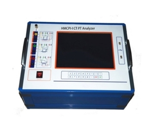
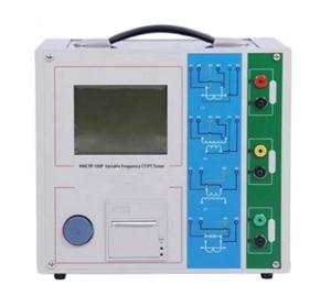
Current Transformer Tester Principle
During the process of supplying and using power, the current magnitude in the current transformer tester varies greatly, ranging from a few amperes to tens of thousands of amperes. In order to facilitate accurate measurements of instruments and dashboards, it must be converted into a more uniform current. Additionally, the working voltage on the power supply circuit lines is relatively high. For example, instant accurate measurements are very dangerous for all instruments, dashboards, and personnel. Therefore, the current transformer tester in this design scheme has the function of isolating the current transformer and electrical equipment.
Most analog current-to-digital display instruments are at the ampere level, so the secondary current of the current transformer tester is mostly at the ampere level (such as 5A, etc.), while the data signals sampled by electronic computers are generally at the milliampere level (0-9V, 4-50mA, etc.). Therefore, a small current transformer tester (with a secondary current rating of milliamperes) is chosen as the bridge between the current transformer detection device and the data signal sampled by the electronic computer for secondary conversion of the current.
The current transformer tester consists of a primary electromagnetic coil, a secondary electromagnetic coil, a core, insulation support points, and outgoing terminal blocks. The core of the current transformer tester is made of laminated ferrite core. Its primary electromagnetic coil is connected in series with the main power circuit, and according to the measured current I1, it generates alternating magnetic flux in the core, combining the two. The secondary electromagnetic coil induces a corresponding secondary current I2 (with a rated voltage of 5A). Neglecting losses from the excitation regulator, I1n1=I2n2, where n1 and n2 are the number of turns of the primary and secondary electromagnetic coils, respectively. The transformation ratio of the current transformer tester is K=I1/I2=n2/n1. Since the primary electromagnetic coil of the current transformer tester is connected to the main power circuit, the primary winding must be grounded with insulation material consistent with the working voltage of the primary circuit to ensure the safety of the secondary circuit and personnel. The secondary circuit consists of the secondary electromagnetic coil of the current transformer tester, dashboards, and the current electromagnetic coil of the automotive relay connected in series. The current transformer tester can be roughly divided into two types: one for accurate measurement and one for maintenance.


