
In the world of electronics, a function signal generator stands as a versatile tool, capable of producing a variety of waveforms that serve as fundamental building blocks for testing, troubleshooting, and experimentation. Whether you're an electronics enthusiast, engineer, or student, understanding how to effectively use a function signal generator is an essential skill. This comprehensive guide will walk you through each step, ensuring you harness the full potential of this indispensable device.
Function Generators Basics
What is a Function Signal Generator?
A function signal generator is an electronic device designed to produce various types of waveforms, each characterized by its distinct shape, frequency, and amplitude. These waveforms, including sine, square, triangle, and pulse, are crucial for simulating real-world electronic signals and conducting a wide range of tests.
Setting Function Generator
Power Source and Electrical Requirements
- Ensure the function generator is connected to a stable power source according to manufacturer guidelines.
- Adhere to recommended voltage and current settings to prevent damage.
Connection to External Devices
- Connect the function signal generator to other devices using appropriate cables and connectors.
- Maintain proper signal integrity and minimize interference.
Grounding and Safety Precautions
- Proper grounding helps mitigate electrical noise and ensures user safety.
- Follow safety protocols to prevent electrical hazards during operation.
Function Generator Usage
Please check whether the power supply voltage is 220V before use, and plug the power cord into the power socket on the rear panel of the instrument only after it is correct.
Ⅰ: Power on
After plugging in the 220V AC power cord, press the power switch on the panel, the frequency display window will show "1642", and the whole machine will start to work.
Ⅱ: Function signal output setting
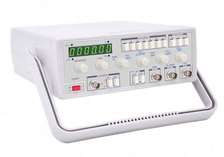
- Frequency setting: Press the frequency gear shift key (RANGE), select the frequency band of the output function signal, and adjust the frequency trim knob (FREQ) to the desired frequency. When adjusting, you can learn the output frequency by observing the frequency display window, as shown in Figure 8-29.
- Waveform Setting: Press the waveform selection button (WAVE) to select Sine, Rectangular or Triangle waveforms in turn, at this time the oscilloscope screen will display Sine, Square and Triangle waveforms respectively.
- Amplitude setting: Adjust the output amplitude adjusting knob (AMPL), by observing the amplitude display window, adjust to the desired signal amplitude. If the desired signal amplitude is small, press the attenuation selection button (ATT) to attenuate the signal amplitude.
- Symmetry setting: Adjust the symmetry (duty cycle) adjustment knob (DUTY) to change the symmetry of the output function signal. The adjustment can improve the distortion of sine wave, make the triangular wave FM become sawtooth wave, and change the symmetry characteristics such as duty cycle of rectangular wave.
- DC Bias Setting: By adjusting the DC offset (DC bias) knob (DCOFFSET), the DC component can be added to the output signal, and the level range of the output signal can be changed by adjustment.
- TTL signal output: the signal output from the TTL output socket (TTL) is a synchronized standard TTL level signal with the same frequency as the function signal output.
- Power Signal Output: The signal output from the power output socket (POWOUT) is a signal that is fully consistent with the function signal output, and can provide 5W output power when the frequency is within the range of 0.6Hz~200kHz, such as the frequency in the 7th gear, the power output signal is automatically turned off.
- Protection Note: When the function signal output or power signal output connected to the load, there is no output signal, indicating the presence of high-pressure signals on the load or load short-circuit, the machine is automatically protected, when troubleshooting the instrument automatically return to normal operation.
Ⅲ: Frequency measurement
- Internal measurement: Press the counter function selection button (FUN), select the internal frequency measurement state, at this time, "INT" indicator lights up, indicating that the counter into the internal frequency measurement state, at this time, the frequency display window shows the frequency of the instrument's function signal output.
- External Measurement: For external frequency measurement, there are two ranges: 1Hz~10MHz and 10~1000MHz. Press the counter function selection button to select the external frequency measurement state, "EXT" indicator will light up to indicate the external frequency measurement, and the measurement range is lHz~10MHz; "EXT" and "1MHz" will light up to indicate the external frequency measurement state, and "INT" indicator will light up to indicate the external frequency measurement state. EXT" and "1GHz" indicator light up at the same time indicates the external measurement of high frequency, the measurement range of 10~1000MHz, the measurement results are displayed in the frequency display window. If the amplitude of the measured signal is greater than 3V, the input attenuation circuit should be turned on, and the attenuation circuit can be selected by the external frequency measurement input attenuation key (ATT), and the external frequency measurement input attenuation indicator will light up to indicate that the external frequency measurement input signal has been attenuated by 20dB. The external frequency measurement is an equal-precision measurement, and the frequency measurement gate will be switched automatically, so it does not need to be changed manually.
Function Signal Generators Application
Function signal generators play a vital role in multiple industries and fields:
- Electronics Engineering: Used for testing and validating circuit behavior.
- Telecommunications: Generate modulated signals for communication systems testing.
- Audio Engineering: Useful in audio equipment testing and development.
- Scientific Research: Assist in controlled signal generation for experiments.
The function generator is a widely used and important measurement instrument, to learn more about the instrument go to sisco.com.


