
In the vast landscape of networking, ensuring a seamless and reliable connection is paramount. Network cable testers play a crucial role in this process, serving as indispensable tools for technicians and IT professionals. In this blog post, we'll delve into the inner workings of these devices, exploring the key mechanisms that make them essential for maintaining robust network infrastructures.
Understanding the Basics
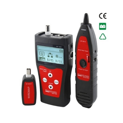
At its core, a network cable tester is designed to examine and verify the integrity of network cables. This includes Ethernet cables commonly used in local area networks (LANs) and other data communication systems. The tester evaluates various aspects of a cable's performance, identifying issues such as continuity, miswiring, and even the length of the cable.
Working principle
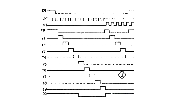
The CD4017 is a widely used decimal counter/pulse distributor with versatile applications. Its timing waveform and pin arrangement diagrams are shown in Figure 2 and the bottom right figure, respectively. From the waveform diagram, it is evident that it has two clock pulse input terminals, namely CP and INH, triggered on the rising and falling edges of the input pulses, respectively. CR serves as the asynchronous clear enable terminal; when CR is set to 1, Y0 is at a logic high, and Y1-Y9 are at logic low. When CR is set to 0, the Y terminals exhibit decoded outputs. One CD4017 chip can constitute a sequential pulse generator with 10 beats. If the output YN (N≥2) is directly connected to CR, sequential pulse outputs for N beats can be obtained in the Y0-Y(N-1) segments.
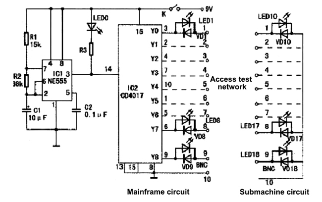
Most local area networks use Unshielded Twisted Pair (UTP) as the transmission medium for networking. The cable consists of a certain length of twisted pair and two RJ45 connectors. The twisted pair comprises 8 wires of different colors, grouped into 4 pairs. To test the continuity and sequence of each wire, as depicted in the accompanying diagram, the circuit can be divided into two parts: the main circuit and the secondary circuit. The 1-8 wiring terminals in the main circuit and the 1-8 wiring terminals in the secondary circuit correspond to the connection points of the tested network cable's two RJ45 connectors (the 9th and 10th wiring terminals in both circuits correspond to the 9th and 10th wiring terminals in the tested network cable's two BNC connectors). The circuit involves LEDs (LED10-LED17 and regular diodes VD10-VD17) assembled in conjunction. This is primarily to complement the operation of the main circuit.
Upon powering up, the NE555 starts working, generating a square wave, and LED0 flashes. Its rising edge triggers the CP terminal of CD4017, and since CR is grounded, the Y terminals exhibit decoded outputs. Only one high level circulates through the output terminals (Y0-Y9), while the others remain at low levels. As per the circuit diagram, it forms the following loop: LED1 → the first wire of the tested network cable → LED10 in the secondary circuit → one of VD11-VD17 → the other wire of the tested network cable → LED2-LED8 in the main circuit. If LED1 in the main circuit is lit, and LED10 in the secondary circuit is also lit, it indicates that the first wire of the tested network cable is "connected," and the same logic applies to the other wires. During network cable testing, any unlit LED1-LED8 signifies a non-functional path. If LED10-LED17 are not sequentially lit, it indicates a wiring sequence error. Furthermore, with practice, the quality of the network cable can be judged based on the intensity of the LED emissions.
The BNC coaxial cable detection example is similar. When the tester is kept in the powered-on state, it will continuously and automatically repeat the testing of the network cable.
How to create a network test tool using CD4017:
In this circuit, IC1 is chosen as NE555, and IC2 is chosen as CD4017. LED0 uses a φ5mm red LED, while LED1-LED18 use φ3mm green LEDs. Additionally, for easy connection to the test network cable, two RJ45 jack boxes should be prepared. The power supply adopts a 9V stacked battery. No special requirements for other components.
After circuit debugging, drill 10 holes on the front panel of the RJ45 jack box of the main unit's casing according to the diameter of the LEDs. On the front panel of the RJ45 jack box of the secondary unit's casing, drill 9 holes based on the diameter of the LEDs. First, insert the LEDs into the holes, then solder each component according to the circuit diagram using wires. Finally, following the two wiring standards (568A and 568B) specified in the EIA/TIA wiring standards, choose one standard and solder the corresponding pin numbers of the 8 pins on the RJ45 jack to the 1-8 wiring terminals of the main unit and the secondary unit. This sequence is crucial during cable testing and must not be mistaken. Since the maximum transmission distance of twisted pair cables is generally 100m, during online debugging, a network cable of approximately 100m can be used for testing.


