
In the dynamic world of networking, ensuring the reliability and efficiency of your connections is paramount. One indispensable tool in the networking toolkit is the network cable tester. Using an ethernet cable checker is a straightforward process that involves a few key steps. Here's a step-by-step guide to help you effectively use a network cable tester:
Functions
Test each pair of twisted lines 1, 2, 3, 4, 5, 6, 7, 8, and the grounding line (G), distinguishing and determining miswiring, short circuits, and open circuits.
The ON switch provides normal testing speed, "S" indicates slow testing speed, and "M" is manual mode.
Twisted Pair Testing
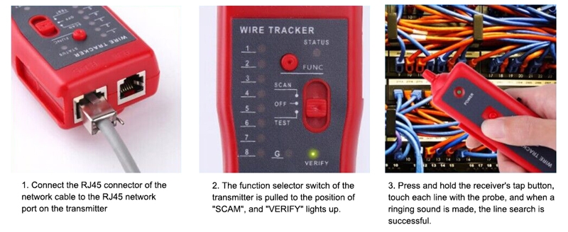
Turn on the power and insert the network plug into both the main tester and the remote tester. The main tester indicator lights sequentially from 1 to G.
Main Tester: 1-2-3-4-5-6-7-8-G
Remote Tester (RJ45): 1-2-3-4-5-6-7-8-G
(RJ12): 1-2-3-4-5-6
(RJ11): 1-2-3-4
If the wiring is abnormal, the display is as follows:
If a wire, such as wire 3, is open, both the main tester and the remote tester will not light up at wire 3.
If several lines are not connected, none of the corresponding lights will light up. When fewer than 2 wires are connected, no lights will be on.
If the wires at both ends are scrambled, for example, if wires 2 and 4 are swapped, the display will be as follows:
Main Tester remains the same: 1-2-3-4-5-6-7-8-G
Remote Tester becomes: 1-4-3-2-5-6-7-8-G
If there are 2 short-circuited wires, the main tester will not light up, and the remote tester will show a slight glow on the lights of the two short-circuited wires. If there are 3 or more (including 3) short-circuited wires, the lights of all the short-circuited wire numbers will not light up.
Caution
When testing patch panels and wall-mounted modules, two matching jumper wires (such as 110P4-RJ45) need to be connected to the tester.
Ethernet Cable Tester Usage Instructions:
An Ethernet cable tester is a tool utilized by network engineers, electricians, and electrical maintenance workers for measuring network cables. It can detect connectivity issues, determine cable lengths, identify cable faults, and assess signal quality. Here are the instructions for using an Ethernet cable tester:
Preparatory Steps
- Understand Cable Types: The Ethernet cable tester is compatible with various cable types, including common cables such as RJ11, RJ45, CAT5, CAT5e, CAT6, CAT7, etc.
- Confirm Measurement Standards: Select measurement standards based on user requirements, including transmission speed, distance, return loss, NEXT, FEXT, etc.
- Choose the Correct Cable Standard: Select the cable standard that matches the measured cable, preventing measurement errors.
- Check Equipment Integrity: Ensure both the equipment and cables are undamaged for accurate measurement results.
Operating Procedure
Powering On the Network Cable Tester
Press the green power button to turn on the network cable tester, ensuring a stable power supply.
Selecting the Test Function
Choose the desired test function based on your requirements, such as cable continuity testing, cable length measurement, cable fault testing, etc.
Connecting the Cable to be Tested
For CAT5/5e/6 cable testing, insert one end of the cable into the "Main Testing" port on the tester and connect the other end to the device being tested. For RJ11 telephone line testing, insert the cable into the "Main Testing" port.
Cable Measurement
- Continuity Testing: After connecting the cable to be tested, press the "Test" button. The network cable tester will verify the connection quality and identify the cable type.
- Length Measurement Testing: Select the length measurement function, place the main unit at one end, and insert the cable into the RF interface at the other end. Press the "Test" button, and the measured length will be displayed on the main unit. Note: This function only supports UTP STP twisted pair cables.
- Cable Fault Testing: Fault testing includes various scenarios such as short circuits, open circuits, reversed wires, misaligned wires, and more. Choose the fault testing function, press the test button, and the network cable tester will provide relevant prompts.
Recording Measurement Data
After completing the cable measurement, record the measurement data as needed. This facilitates quicker and more accurate identification of cable faults during future projects and aids in project acceptance and subsequent maintenance.
Concluding the Operation
Closing the Tester
Press the power button to turn off the network cable tester after completing a series of measurement tasks.
Storage of Equipment
Store the cable tester, connectors, and cables securely, keeping them clean and dry for future use.
By following these steps, you can effectively use a Network Cable Tester to ensure the integrity and functionality of your network cables. Regular testing is crucial for maintaining a reliable network and quickly addressing any connectivity issues. For more knowledge about test equipment, please go to sisco.com.


