
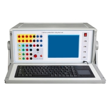
A relay tester is a specialized piece of equipment designed to test, validate, and troubleshoot relays and their associated components. Relays are electromechanical or solid-state devices that control the flow of current within an electrical circuit. They serve a critical role in various applications, such as protecting equipment, controlling motors, and managing power distribution.
The Key Components of a Relay Tester
-
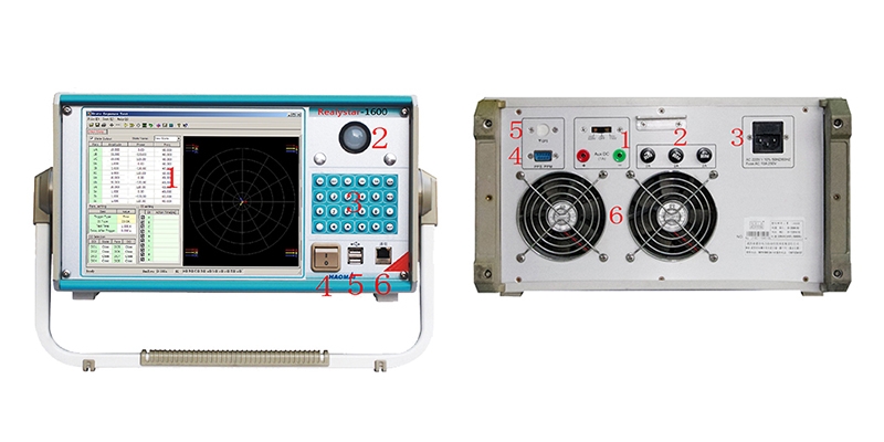
Front panel of 6 phase relay tester
- TFT LCD display
- Track ball mouse, left and right key of track ball mouse
- Faceplate optimized keyboard
- Power supply switch
- USB interface: it can be connected with external equipment like mouse, keyboard, flash disk, printer, etc
- 10-100M net terminal: it can be connected with outer PC to doing test
- Rear panel of 6 phase relay tester
- Auxiliary DC power supply output: it can be switched to 110V or 220V, and can be used as on-the-spot testing power supply
- Voltage output fuse
- AC 220V operational power supply socket
- PPS
- Communication port with outside GPS device
- Wind outlet of cool fan
Features
Relays are used in a wide range of applications where the consequences of a failure can be catastrophic. Imagine a relay failing to open in a high-voltage circuit, causing electrical damage or even fires. Relay testers are essential for several reasons:
- Safety Assurance: In many applications, such as power distribution and industrial automation, relays play a critical role in controlling electrical currents. Ensuring that relays function as intended is paramount for the safety of personnel, equipment, and the environment. Malfunctioning relays can lead to electrical accidents, fires, and other safety hazards.
- Reliability Enhancement: Relays are often used in systems where failure is not an option. For example, they are vital in critical systems like emergency shutdowns, aviation, and medical equipment. Relay testers help identify potential issues before they lead to system failures, thus enhancing the overall reliability of these systems.
- Preventive Maintenance: Regular testing with relay testers allows for the early detection of problems or degradation in relay performance. This proactive approach enables maintenance professionals to address issues before they cause unexpected downtime or damage, thereby reducing maintenance costs and prolonging equipment life.
- Troubleshooting and Diagnostics: When relay-related issues do occur, relay testers are invaluable for diagnosing the root causes quickly. This aids in the swift restoration of system functionality.
Relay Tester Working Principles:
Relay protection testing instruments consist of two circuits: the main circuit and the auxiliary circuit. The main circuit is adjusted using a large knob, while the auxiliary circuit is adjusted using a small knob. The main circuit's various output parameters are controlled by the "Output Selection" button on the panel. Whenever a different output is selected, the digital voltage/current meter on the instrument automatically monitors the output values. The auxiliary circuit is controlled by an output switch, allowing direct adjustment of the output, and measurements can be taken using an external multimeter.
1. Microcomputer Relay Protection Testing Instrument - Main Circuit Principle:
The input AC 220V power source passes through a fuse and enters the double carbon brush voltage regulator T1. The regulated output from T1 is adjusted by the large knob and enters the isolation transformer T2. T2 has three tap settings: the first tap provides AC 0-250V output with a rated current of 3A. The voltage output from this tap can be rectified and filtered to provide 0-350V DC voltage. The second tap provides 15V (10A), with one branch controlled by a sensor and relay to output 0-10A AC current, another branch through a resistor to output 0-500mA AC current, and a third branch can switch to provide 0-10A or 0-500mA DC current. The third tap provides 10V (100A) high-current output, which, when passed through a sensor, directly outputs 100A current on the secondary side. This circuit has a strong load capacity but should not be operated in a high-current state for extended periods.
2. Microcomputer Relay Protection Testing Instrument - Auxiliary Circuit:
The auxiliary circuit of the relay protection testing instrument operates similarly to the main circuit. The AC 220V power source passes through a fuse and enters the double carbon brush voltage regulator T1, where the voltage is adjusted using the small knob. The output can be directly adjusted through the isolation transformer T4 to provide 0-20V or 0-250V AC voltage, 0-350V DC voltage, with a rated current of 1A. Pressing the "Output Control" switch for the auxiliary circuit allows you to adjust the output using the small knob.
The above is the relevant information about relay testers. If you want to know more about relays, please go to sisco to learn more.


