
Conductivity meters are powerful instruments that provide valuable insights into the electrical conductivity of solutions, playing a vital role in various scientific and industrial applications. In this blog post, we will guide you through the essential steps on how to effectively use a conductivity meter, from preparation to interpretation of results.
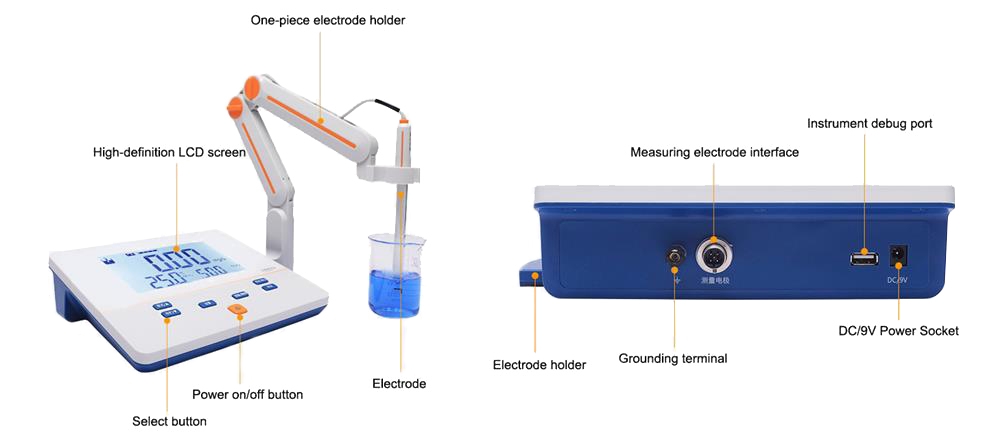
Understand the basic components
Steps
- Before turning on the power switch, observe whether the meter needle points to zero. If it does not point to zero, adjust the screw on the meter head to make the meter point to zero.
- Turn the calibration and measurement switch to the "Calibration" position.
- Plug in the power cord, turn on the power switch, and preheat for a few minutes (until the pointer is completely stable) and adjust the "adjustment" device to make the meter indicate full scale.
- When using the (1) ~ (8) range to measure liquids with conductivity lower than 300, select "Low Cycle", then just turn the plate to "Low Cycle". When using the (9) ~ (12) range to measure liquids with conductivity in the range of 300 to 300, turn it to "high cycle".
- Turn the range selector switch to the required measurement range. If you do not know the conductivity of the solution being measured in advance, you should first turn it to the maximum conductivity measurement range, and then lower it step by step to prevent the meter needle from bending.
- Measurement reading: Generally, the knob for measuring the "constant" is turned to 1.0, and the adjustment (ADI) is turned to the maximum value before measurement, and then slowly adjusted, and the measuring switch is turned to the calibration position to adjust the zero point. Select the range, turn the measuring switch to the measuring position and then take the reading.
- Use of electrodes: When using, use the electrode clamp to clamp the bakelite cap of the electrode, and fix the electrode on the electrode rod through the electrode clamp. (1) When the conductivity of the solution being measured is lower than 10, use DJS-1 type bright electrode. At this time, R should be adjusted to the position corresponding to the constant term of the matching electrode. For example, if the constant of the mating electrode is 0.95. Then R should be adjusted at 0.95, just like if the constant of the matching electrode is 1.1, R should be adjusted at 1.1. (2) When the conductivity of the solution being measured is in the range ~, use DJS-1 type platinum black electrode. Same as (1) R should be adjusted at a position corresponding to the constant of the matching electrode. (3) When the conductivity of the measured solution is greater than , so that it cannot be measured with the DJS-1 type platinum black electrode, the DJS-10 type platinum black electrode is used. At this time, R should be adjusted to the constant position of the matching electrode. For example: If the constant of the electrode is 9.8, then R should be pointed at 0.98. Then multiply the measured reading by 10 to obtain the conductivity of the solution being measured.
- Insert the electrode plug into the socket, tighten the fastening screw on the socket, and then immerse the electrode in the solution to be measured.
- Then calibrate (when measuring with (1) ~ (8) range, the calibration is at low cycle. When measuring with (9) ~ (12) range, then calibrating is at high cycle), and it is about to reach "Calibrate", adjust the indicator needle to full scale. Note: In order to improve the measurement accuracy, when using the "×" and "×" gears, calibration must be performed with the conductivity cell properly connected (the electrode plug is inserted into the jack and the electrode is immersed in the solution to be measured).
- After that, turn to measure. At this time, the indicated number multiplied by the magnification of the range switch is the actual conductivity of the liquid to be measured. For example, if the meter is set to 0~0.1 and the pointer indicates 0.6, the conductivity of the liquid to be measured is 0.06 (0.6×0.1 = 0.06). If the meter is set to 0 to 100 and the meter indicates 0.9, the conductivity of the liquid to be measured is 0.6. The conductivity is 90 (0.9×100 =90), and so on.
- When measuring high-purity water with the two levels of 0~0.1 or 0~0.3, first insert the electrode lead into the electrode jack, and before the electrode is immersed in the solution, adjust the meter so that the meter indicates the minimum value (this minimum value is the electrode platinum piece Due to the existence of this leakage resistance, the pointer of the time adjustment meter cannot reach zero). Then start measuring.
- If you want to know the changes in conductance during the measurement process, just connect the 10mV output to the automatic potentiometer.
- When the range switch is set to "×0.1", set it to low cycle. However, when the conductivity cell socket is not connected to an electrode, the ammeter will have an indication. This is a normal phenomenon because there is capacitance in the electrode socket and wiring. Just adjust: "Capacitance compensation" to adjust this indication to zero. You don't have to do this. Just wait until the electrode lead is inserted into the socket, and then adjust the indication to the minimum value.
- When using each gear (1), (3), (5), (7), (9), (11), look at the scale (0~1.0) on the surface; and when using (2), ( 4), (6), (8), (10) for each gear, look at the scale (0~3) below the surface.
Effectively using a conductivity meter involves careful preparation, proper setup, and accurate interpretation of results. If you need more professional guidance, please go to sisco.com. By following these steps, you can harness the full potential of conductivity meters in various scientific, industrial, and environmental applications.


