
Although oscilloscopes are divided into several categories, each type has many models, but the general oscilloscope in addition to bandwidth, input sensitivity, etc. are not exactly the same, in the use of the basic aspects of the method are the same. In this comprehensive guide, we will delve into the ins and outs of using an oscilloscope effectively.
Adjustment Procedures
1. Brightness and Focus Knobs: The brightness control knob adjusts the brightness of the trace (sometimes referred to as "intensity"). Suitable brightness should be chosen to avoid damaging the cathode-ray tube. The focus adjustment knob is used to focus the trace for clear graphics.
2. Signal Input Channels: Common oscilloscopes, such as SISCO-DSCO oscilloscopes, often have dual-trace capability with two input channels labeled Channel 1 (CH1) and Channel 2 (CH2). These channels are connected to the oscilloscope probes, which are grounded by connecting them to the oscilloscope's chassis. The probes are then inserted into the points to be tested for measurement.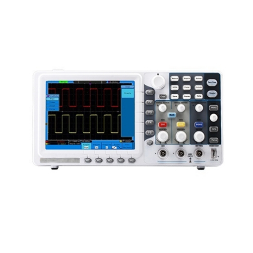
3. Channel Selection Key (Vertical Mode Selection): Most oscilloscopes have five channel selection modes:
- CH1: Display Channel 1 alone.
- CH2: Display Channel 2 alone.
- ALT: Alternately display both channels.
- CHOP: Display channels alternately, suitable for slow-scan dual-trace display.
- ADD: Overlay the signals from both channels. During maintenance, prefer using Channel 1 or Channel 2.
4. Vertical Sensitivity Adjustment Knob: Adjust vertical deflection sensitivity based on the input signal amplitude. Multiply the knob indication value (e.g., 0.5V/div) by the number of divisions occupied by the signal in the vertical direction to determine the signal's amplitude.
5. Vertical Position Adjustment Knob: Used to adjust the vertical position of the measured signal trace on the screen.
6. Horizontal Sweep Adjustment Knob: Adjust the horizontal sweep speed according to the input signal frequency. Multiply the knob indication value (e.g., 0.5ms/div) by the number of divisions occupied by the signal in one period to determine the signal's period or frequency.
7. Horizontal Position Adjustment Knob: Used to adjust the horizontal position of the signal trace on the screen.
8. Trigger Four Modes: Oscilloscopes typically offer four triggering modes:
- NORM: Displays a stable waveform by controlling levels when a signal is present.
- AUTO: Displays a trace even when no signal is present, achieving stable display with level control.
- TV: Used to display television field signals.
- PEAK AUTO: Displays a trace even when no signal is present, maintaining stability without level adjustment. This method is only used in certain oscilloscope models.
9. Trigger Source Selection: There are two trigger sources: internal and external. For external trigger, the trigger signal is provided from an external source. For internal trigger, select the appropriate channel (CH1 or CH2) based on the input signal channel.
Measurement Methods
1. Probe and Channel Setup: Insert the oscilloscope probe into the CH1 input socket and set the coupling mode to DC for CH1.
2. Connect Calibration Signal Source: Insert the probe tip into the small hole of the calibration signal source. A trace will appear on the oscilloscope screen.
3. Adjust for Stable Display: Use vertical and horizontal knobs to achieve a stable waveform display.
4. Measure Amplitude: Read the number of divisions occupied by the waveform in the vertical direction. Multiply this by the vertical attenuation knob's indication value to determine the calibration signal's amplitude.
5. Measure Frequency: Read the number of divisions per cycle in the horizontal direction. Multiply this by the horizontal sweep knob's indication value to determine the calibration signal's period (frequency reciprocal).
Special Usage Methods
1. AC Peak Voltage Measurement: Calculate peak voltage using the formula: Voltage (p-p) = Vertical deflection amplitude/div x (VOLTS/div) x Attenuation ratio.
2. Rise Time Measurement: Calculate rise time using the formula: Rise time = Horizontal distance/div x Time/div (time per division) x Extender factor.
3. Phase Difference Measurement: Calculate phase difference using the formula: Phase difference = Horizontal difference/div x Horizontal calibration value/div.
Pre-use Check for Oscilloscope
1. Perform Basic Adjustments: Adjust brightness, focus, vertical channel selection, horizontal sweep time factor, etc.
2. Obtain Baseline: Ensure a fine and bright scan baseline is achieved, positioned in the middle of the screen coinciding with the horizontal coordinate scale.
3. Display Signal: Connect the probe to the standard square wave signal output of the oscilloscope. Adjust voltage range and sweep time factor to observe signal changes.
4. Measure Signal: Connect the probe to CH1 or CH2 and touch the test point. Adjust voltage range and sweep speed to observe the waveform.
Please note that specific procedures may vary based on the oscilloscope model and its features.
Mastering the use of an oscilloscope empowers you to explore the hidden details of electrical signals, paving the way for efficient circuit debugging, design optimization, and insightful analysis. A wide variety of oscilloscopes are sold at sisco to meet your needs. Whether you're analyzing complex waveforms or verifying the performance of electronic components, the oscilloscope is your invaluable tool for bringing the invisible world of electrical signals into clear view.


