
Digital oscilloscopes are the cornerstone of modern electronics, providing engineers and technicians with an indispensable tool to peer into the intricacies of electrical signals. To truly understand how these devices work, let's embark on a comprehensive journey through the various stages of signal acquisition, digital processing, and waveform visualization.
Signal Acquisition
- Input Channels: At the forefront of signal acquisition are the input channels. These are the pathways through which the oscilloscope connects to the circuit under examination. Each input channel consists of a probe that interfaces with the circuit and captures the analog voltage signal. The signal is then ready for digitization.
- Analog-to-Digital Converter (ADC): The captured analog voltage signal is inherently continuous in nature, but digital oscilloscopes operate in the digital realm. This transition from analog to digital is achieved through an Analog-to-Digital Converter (ADC). The ADC samples the analog signal at regular intervals, known as the sample rate, and assigns a digital value to each sample point. The resulting collection of digital values represents a discrete version of the continuous waveform.
- Sample Rate and Bandwidth: The sample rate is a crucial parameter that governs the rate at which the ADC takes samples of the analog signal. The Nyquist theorem dictates that the sample rate must be at least twice the frequency of the highest component of the signal to avoid aliasing. Alongside sample rate, the oscilloscope's bandwidth is equally important. It defines the range of frequencies that the oscilloscope can accurately capture. A wider bandwidth ensures faithful representation of higher frequency components within the signal.
Digital Signal Processing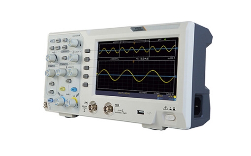
- Memory: The digitized samples are stored in the oscilloscope's memory for subsequent processing and visualization. The depth of the memory determines how much of the signal can be captured and retained for analysis. Deeper memory enables the oscilloscope to store longer durations of captured signals while maintaining a high sample rate.
- Triggering: Triggering is an essential aspect of oscilloscope operation. It serves to stabilize the displayed waveform by synchronizing the trigger point with a specific event within the signal. Common trigger conditions include rising or falling edges of pulses, specific voltage levels, and pulse width thresholds. Triggering ensures that the same portion of the waveform is consistently displayed, aiding in analysis and troubleshooting.
Waveform Visualization
- Display: The culmination of the oscilloscope's efforts is the visual representation of the waveform on the display screen. This screen acts as the canvas where voltage is plotted on the vertical axis and time on the horizontal axis. Engineers can adjust the vertical and horizontal scales to focus on specific details of the waveform. The ability to zoom in and out allows for detailed examination of signal behavior.
- Waveform Processing: Digital oscilloscopes offer a wide array of waveform processing options. Filtering tools allow engineers to eliminate noise and focus on the core signal. Averaging functions help smooth out variations caused by noise, resulting in clearer waveforms. Mathematical operations, such as addition, subtraction, multiplication, and differentiation, can be performed on multiple waveforms, aiding in advanced signal analysis.
Advanced Features
- Math Functions: Mathematical functions enable engineers to perform calculations on waveforms, offering insights beyond simple visual analysis. These functions allow for operations such as addition, subtraction, multiplication, and integration. Engineers can overlay multiple waveforms and analyze their relationships mathematically.
- FFT (Fast Fourier Transform): The FFT function is a transformative tool that converts time-domain waveforms into frequency-domain representations. This reveals the frequency components present within the signal, allowing engineers to identify specific frequencies and harmonics.
- Protocol Analysis: Some oscilloscopes are equipped with protocol decoding capabilities. These functions enable engineers to analyze and interpret digital communication protocols such as UART, SPI, I2C, and CAN. The oscilloscope deciphers and displays the transmitted data in a human-readable format, greatly simplifying the debugging of digital communication interfaces.
Digital oscilloscopes are signal generators & analysers that encompass a series of intricate steps to capture, process, and visualize electrical signals. By understanding the nuances of signal acquisition, digital conversion, processing, and advanced features, engineers can harness the power of oscilloscopes to uncover the hidden aspects of electronic systems, leading to innovative designs, enhanced troubleshooting, and continuous progress in the field of electronics.


