
When connecting the optical time domain reflectometer (OTDR) to the test pigtail, first clean the pigtail on the test side, then insert the pigtail into the test socket of the vertical instrument, and return the raised U-shaped part of the pigtail to the test socket. Type sections are fully connected and properly tightened. When the line is repaired or cut over, before the optical fiber under test is connected to the OTDR, the maintenance personnel at the opposite station of the trunk section should be notified to remove the corresponding connecting pigtail on the optical fiber distribution box to avoid damage to the optical disc.
- Wavelength selection setting: select the wavelength required for the test, there are two wavelengths of 1310nm and 1550nm for selection.
- Distance setting: first test the optical fiber in automatic mode, and then set the test distance according to the length of the test fiber, usually 1.5 times the actual distance, mainly to avoid false reflection peaks that affect judgment.
- Pulse width setting: the optional pulse width generally has 10ns, 30ns, 100ns, 300ns, 1μs, 10μs, and other parameter options. The smaller the pulse width, the shorter the sampling distance and the more accurate the test, otherwise the longer the test distance, the less accuracy is relatively small. According to experience, generally, 100ns and below parameters are selected below 10KM, and 100ns and above parameters are selected above 10KM.
- Sampling time setting: The longer the sampling time of OTDR, the smoother the curve and the more accurate the test.
- Refractive index setting: it depends on the requirements of each transmission line.
- Event threshold setting: it refers to pre-setting the attenuation of the connection point or loss point of the optical fiber during the test. When there is an event exceeding the threshold, the instrument will automatically analyze and locate it.
Precautions for using optical time domain reflectometer
- The optical time domain reflectometer (OTDR) emits high-energy light signals during operation, so it is forbidden to directly look at the port with the eyes during the test to avoid burning the eyes.
- Keep the test port of the optical time domain reflectometer (OTDR) and the optical port of the optical cable clean to avoid the phenomenon that there is no data in the test, that is, the optical link cannot work normally or the attenuation test is inaccurate.
- The optical time domain reflectometer (OTDR) test port has a built-in ceramic core, which is very fragile, so avoid vigorous twisting and bumping.
- During the testing process of optical time domain reflectometer (OTDR), no signal other than the signal emitted by the instrument is allowed. First, it will interfere with the accuracy of the test, and second, it will damage the optical link equipment.
- Select the appropriate test distance and pulse width. When you don’t know the length of the optical cable, you can use the automatic test function of the instrument to get a general understanding of the quality of the optical cable to be tested, and then manually set reasonable test range and pulse width and other parameters. , used to accurately locate the entire optical cable and the position and loss of each event.
How to solve the blind area of the optical time domain reflectometer?
The blind zone of the Optical Time Domain Reflectometer (OTDR) comes from the Fresnel inverse principle. There are two types of dead zone, event dead zone and decay dead zone. The reflection peak caused by the intervention of the active connector, the distance from the start of the reflection peak to the saturation peak of the receiver is called the event dead zone; the reflection peak caused by the intervention of the active connector in the optical fiber, the distance from the start of the reflection peak to the point where other events can be identified the distance between them is called the attenuation dead zone.
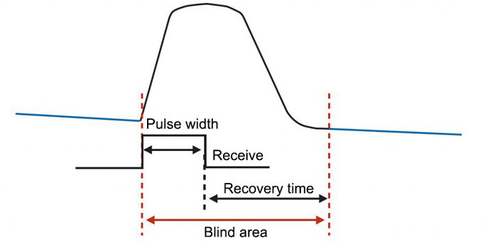
The dead zone is the region of time where the tester is temporarily blinded by a large amount of reflected light until it recovers and can read light again. Since the optical time domain reflectometer (OTDR) works by calculating the length of the cable and the point of failure based on time, a large number of reflections will cause the tester to take more time to recover, which creates a dead zone. The limitations of dead zones make optical time domain reflectometers (OTDRs) largely incapable of troubleshooting.
When testing with an Optical Time Domain Reflectometer (OTDR), blind spots can be addressed with a Visual Fault Locator (VFL). Visual fault locator (VFL) can be used as a supplement to the optical time domain reflectometer (OTDR) in cable troubleshooting, and it can successfully cover the range that the optical time domain reflectometer cannot detect due to dead zone. The Visual Fault Locator (VFL) is designed with a visible laser and a universal adapter for SC, ST, FC, and FJ connectors, making it easy to locate cables, verify cable continuity and polarity, and help find breaks, connectors, and splices in cables point. Therefore, the Visual Fault Locator (VFL) is an ideal solution for solving and locating the blind area of the optical time domain reflectometer.
Measurement Solutions for Optical Time Domain Reflectometers
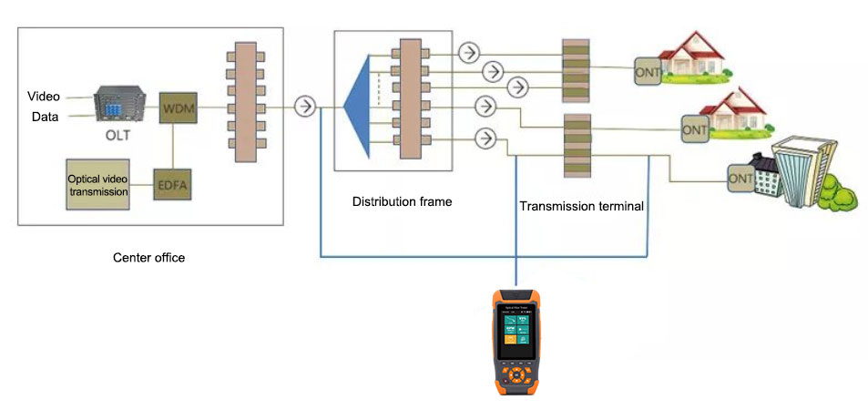
Optical time domain reflectometer (OTDR) is widely used in the maintenance and construction of optical cable lines, and can measure the length of optical fiber, optical fiber transmission attenuation, joint attenuation and fault location. The figure below shows the measurement diagram and solution of optical time domain reflectometer (OTDR).
Line monitoring is an important task to ensure the smooth operation of the optical network. In order to ensure that it is always in the best working condition, regular maintenance of optical cables is required. As the network continues to evolve to a higher transmission rate in the future, the optical time domain reflectometer (OTDR) plays a vital role in ensuring that the optical cable is not replaced frequently during use. sisco.com offers a wide range of functional optical time domain reflectometers, which are essential tools for building, maintaining and monitoring fiber optic cables.


