
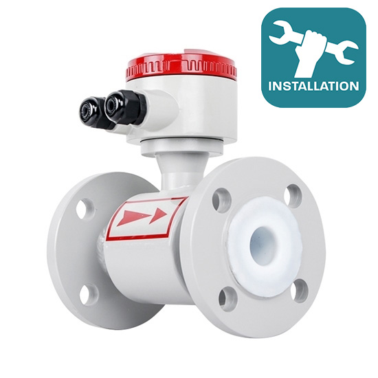
A magnetic flow meter is a type of flow meter that measures the flow rate of a liquid or slurry by measuring the voltage generated when the liquid flows through a magnetic field. The structure of electro magnetic flow meter is mainly composed of magnetic circuit system, measuring conduit, electrode, shell, lining and converter. As the liquid flows through the tube, it generates a voltage proportional to its velocity, which is then measured by the electrodes.
We should not only know what the electromagnetic type flow meter is, but also have some points to pay attention to when installing it. In the following, we will give you some tips about installing this type of flow meter.
Negative Pressure Pipe System Installation
Fluoroplastic lined gauges must be carefully applied to negative pressure piping systems. Positive pressure piping systems should prevent negative pressure, such as when the temperature of the liquid system is higher than room temperature. In this case, close the upstream and downstream shutoff valves of the magnetic flow meter and stop operation. And the meter should be installed close to the negative pressure prevention valve.
Straight Pipe Sections Installation
- First of all, it should be noted that the electromagnetic flowmeter itself cannot be used as a load support point. Instead, a clamp must be added to the side load bearing pipe. Electromagnetic flow meters also require a certain length of straight pipe upstream to achieve normal measurement, but its length is shorter than most other flow meters.
- Second, to prevent the butterfly valve flange from entering the meter measuring tube, use a 900 elbow, T-shaped pipe, concentric reducer, fully open gate valve after the meter that is 5 times the diameter of the flange connection surface from the inlet end (5D) length of the straight pipe section, and a downstream straight pipe section for (2–3) D. The upstream and downstream straight pipe length standards or calibration techniques are also inconsistent, with some magnetic flowmeter requirements that are higher than the typical high requirements. This is to guarantee that the current 0.5 level of instrument accuracy criteria are met.
Position and Flow Direction For Installation
- The installation direction of the flowmeter is unlimited, and it can be installed horizontally, vertically, or obliquely. However, in order to ensure that the processing pipe and the measuring pipe are coaxial. The shaft deviation should not exceed 2 mm. Flow from bottom to top and install vertically.
- In order to protect the magnetic flowmeter lining next to the pipeline from heat and ensure that the instrument converter signal line is not connected, it must be installed horizontally, with the electrode axis parallel to the horizon, rather than perpendicular to the horizon, because there is more likely to be liquid on the top electrode, and the electrode on the ground is more likely to be covered by sediment.


