
Dual channel digital oscilloscope with 200 MHz bandwidth, 2 GSa/s sampling rate, 8 bits vertical resolution. The DSO oscilloscope has cursor measurement function, when manually reading amplitude-frequency parameters, you do not need to read the background scale unit and quantity, and you can directly get the peak-to-peak value and frequency without conversion.
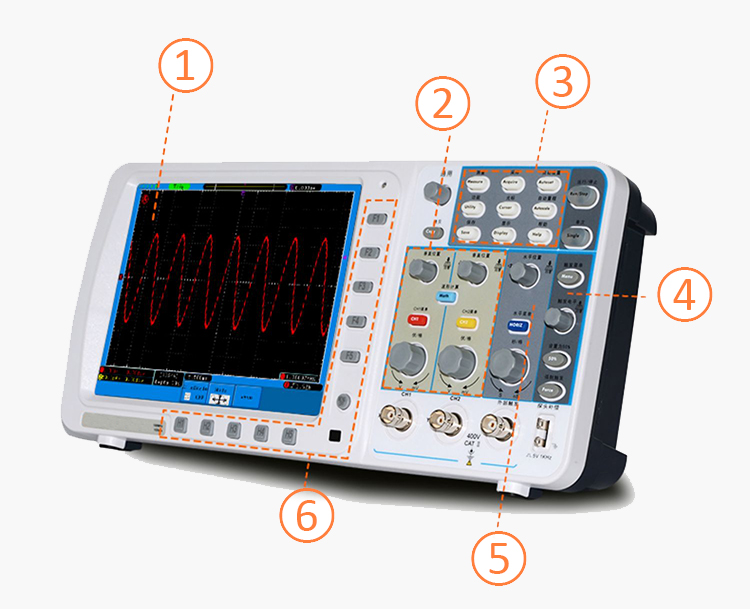
Digital storage oscilloscope interface details
- 8-inch high-resolution LCD
- Vertical control area
- Function key area
- Trigger area
- Horizontal control area
- Function selection button
Support SCPI
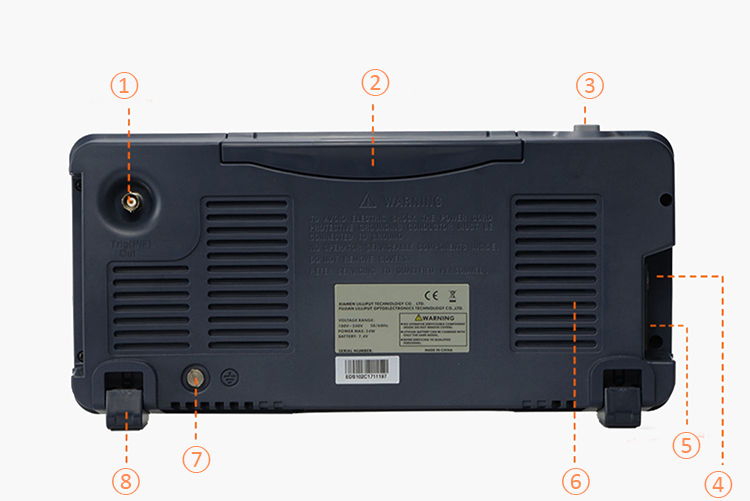
- Trigger output or pass/fail output port
- Stowable handle
- Switch
- Main power switch
- Power socket
- Optimized cooling holes
- Ground port
- Tripod (adjustable oscilloscope tilt angle)
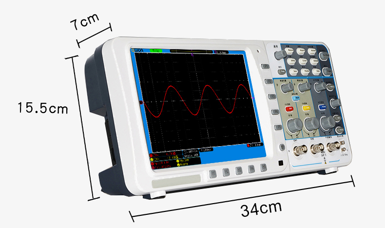
Dimension Unit (mm)
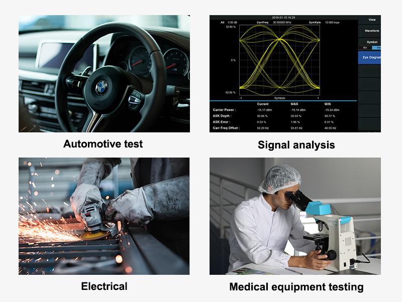
Application
The main application of a SISCO oscilloscope is used to display the waveforms of signals. It can be used in many fields such as automotive test, signal analysis, electrical, transducer test and measurement, electrical equipment design, medical equipment testing field, etc.
| Model | SISCO-EDS-202C |
| Bandwidth | 200 MHz |
| Channel | 2+ external trigger |
| Sample rate | 2 GSa/s |
| Acquisition model | Sample, Peak detect |
| Record length | 10M |
| Display | 8 inch LCD |
| Waveform refresh rate | 10000 wfrms/s |
| Input coupling | DC, AC, Ground |
| Probe attenuation | 1X, 10X, 100X, 1000X |
| Input Impedance | 1MΩ ± 2%, in parallel with 15pF ± 5pF |
| Max. input voltage | 400V (DC+AC, PK - PK) |
| Bandwidth limit(typical) | 20MHz / Full bandwidth |
| Sampling rate range | 2ns/div ~ 100s/div,step by 1-2-5 |
| Vertical Resolution | 8 bits |
| Sensitivity Resolution | 2mV/div~10V/div |
| Low Frequency(-3db) | ≥10 Hz (at input, AC coupling) |
| Rise time (at input, Typical) | ≤1.7ns |
| Trigger type | Edge |
| Trigger model | Auto, Normal, single |
| Trigger level range | ±6 div from the screen center |
| Automatic measurement | Vpp, Vavg, Vrms, Frequency, Period, Vmax, Vmin, Vtop, Vbase, Vamp, Overshoot, Preshoot, Rise Time, Fall Time, +Width, -Width, +Duty, -Duty, DelayA→B , DelayA→B |
| Cursor measurement | ΔV, ΔT, ΔT&ΔV between cursors,auto cursor |
| Dimension | 340*155*70mm |
| Weight | 1.8kg |
Accessories
- Power cable
- USB cable
- Probe
- Probe Adjust
- Quick Guide
Q1: Can an oscilloscope measure DC voltage?
A1: DC voltage can be measured using either an oscilloscope or a digital multimeter. Each piece of testing equipment has its advantages and disadvantages.
Q2: What is the maximum frequency for the oscilloscope?
A2: System bandwidth determines an oscilloscope's fundamental ability to measure an analog signal - the maximum frequency range that it can accurately measure. Entry-level scopes will often have a maximum bandwidth of 100 MHz. They can accurately (within 2%) show the amplitudes of sine-wave signals up to 20 MHz.
Q3: What is the record length for an oscilloscope?
A3: The record length, measured in points or samples, divided by the sample rate (in Samples/second) specifies the total time (in seconds) that is acquired. Example: With a record length of 1 M points and a sample rate of 250 MSa/sec, the oscilloscope will capture a signal of 4 msec in length.
Tips: How to fix a digital storage oscilloscope?
- The measured voltage amplitude is 10 times larger or smaller than the actual value: Check if the attenuation factor in the channel setting menu matches the actual attenuation ratio of the probe used.
- The waveform is displayed, but cannot be stabilized:
- Check if the source item in the trigger mode menu matches the actual signal channel used.
- Check the trigger type item: general signal should use edge trigger mode, and video signal should use video trigger mode. If alternate trigger is selected, the trigger level of both channels should be adjusted at the appropriate position. Only when the suitable trigger method is applied, the waveform can be displayed stably.
- Try to change the trigger coupling to high-frequency suppression and low-frequency suppression to filter out high-frequency or low-frequency noise that interferes with the trigger.
3. Press the Run/Stop key without any display: Check if the trigger mode of the Trigger Mode menu is in Normal or Single and the trigger level is out of the waveform range. If so, center the trigger level or set the trigger mode to Auto. Alternatively, press Autoset to complete the above settings automatically.
Thank you for buying industrial test and measurement equipment on SISCO.com, all products sold by SISCO and the partner cover a 12 months warranty, effective from the date of receiving the products.
What is covered?
SISCO is responsible for providing free spare parts, and free technical support to assist the customer to repair the defective products until the problem is solved.
What is not covered?
- Product purchased from anyone other than a SISCO store or a SISCO authorized reseller.
- Expendable parts.
- Routine cleaning or normal cosmetic and mechanical wear.
- Damage from misuse, abuse or neglect.
- Damage from use of parts other than SISCO approved.
- Damage from use outside the product’s usage or storage parameters.
- Damage from use of parts not sold by SISCO.
- Damage from modification or incorporation into other products.
- Damage from repair or replacement of warranted parts by a service provider other than a SISCO authorized service provider.
- Damage caused by the application environment not meeting the product usage requirements and the failure to perform preventive maintenance.

Shop on sisco.com for all of your industrial test and measurement equipment & accessories including portable detectors, meters, testers, scales, etc.


