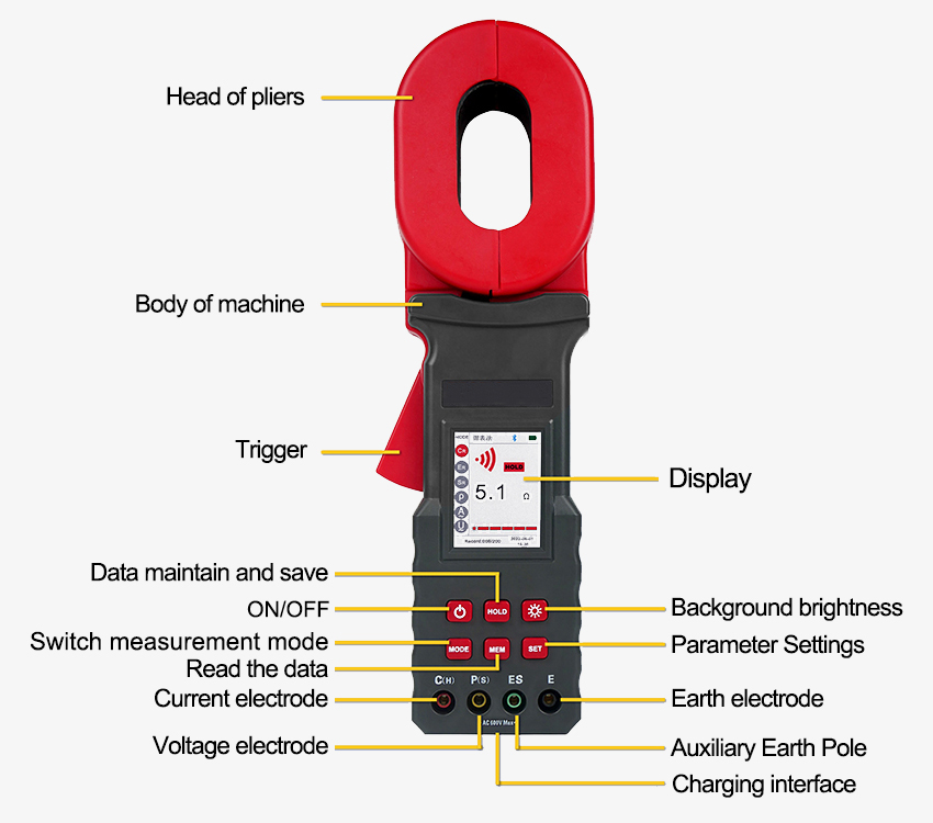
High precision earth resistance tester for sale online. It is equipped with a 0~20kΩ measure range, 5-inch color LCD screen, USB interface charging port, storage function and clock function, used for measuring ground resistance, soil resistivity, ground current and ground voltage on site.

Clamp earth resistance tester is available with a 32mm clamp and 0~20kΩ measure range.
- Clamp earth resistance tester is designed for on-site measurement of ground resistance, soil resistivity, ground current, and the ground voltage.
- The sisco ground resistance tester can measure grounding resistance by various measurement methods such as the clamp meter method, two-wire method, three-wire method, four-wire method, and selection method.
- It uses a 2.5-inch color LCD screen. The resistance tester has a USB interface charging port, storage function, and clock function, and automatically stores 500 groups.
- The ground resistance tester supports the Bluetooth communication function of the Android system. After installing the APP, you can test or read the test records on the mobile terminal.
Applications
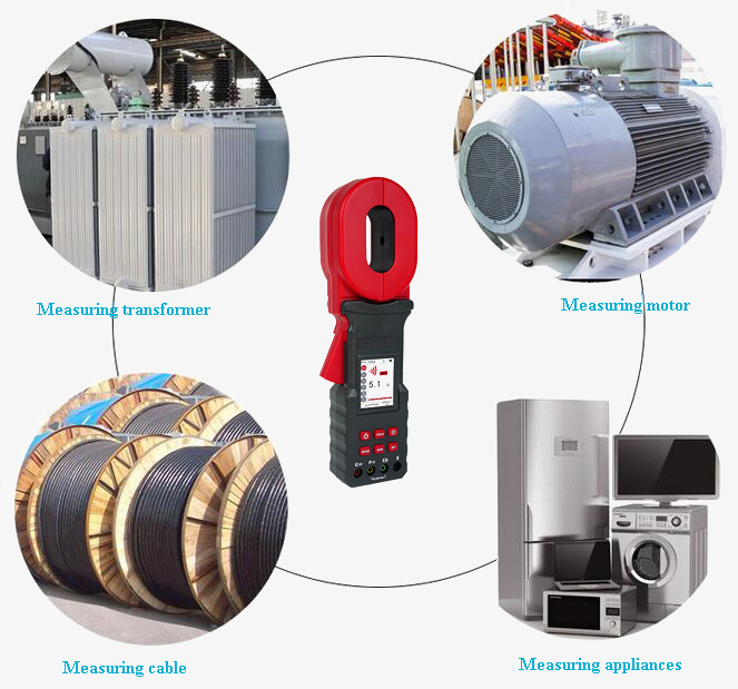
sisco earth resistance tester is available with a measuring range of 0.00Ω-300kΩ. The clamp earth resistance tester is widely applied in ground resistance measurement, and loop resistance measurement in fields such as electric power, telecommunications, meteorology, oil field, architecture and industrial electrical equipment, etc. When measuring the ground system with a loop, there is no need to disconnect the ground wire without an auxiliary electrode.

| Model | SISCO-ERT-2300 |
| Resistance Range | 0.00Ω~20kΩ |
| Soil Resistivity Range | 0Ωm~9999kΩm |
| Ground Current Range | 0.000mA~20A |
| Ground Voltage Range | 0.0V~600.0V |
| Earth Resistance Measurement Methods | Clamp meter method, two-wire method, three-wire method, four-wire method, selection method |
| Test Frequency | 128Hz/111Hz/105Hz/94Hz (AFC automatic frequency selection) |
| Display Mode | 2.5-inch color LCD screen |
| Short Circuit Test Current | AC 10mA max |
| Open Circuit Test Voltage | AC 14V max |
| Electrode Spacing Range | 1m~100m |
| Weight | 5.1 kg |
| Clamp Size | 65mm×32mm |
| Tester Size | 307mm×98mm×56mm |
| Test Line | 4 Pieces (red 20m, black 20m, yellow 10m, green 10m) |
| Simple Test Line | 2 Pieces (red 1.6m, black 1.6m) |
| Auxiliary Ground Rod | 4*Φ9mm×230mm (935g) |
| Measurement Times | more than 5000 times (short circuit test, test once, stop for 30 seconds and test again) |
| Line Voltage | measured below AC 600V |
| Data Memory | 500 groups |
| Audible And Visible Alarm | "du—du—du" for alarming, press AL to turn on/off |
| Automatic Shut-Down | Automatic shutdown after 5 minutes of power on |
| Shift | Automatically |
| External Magnet/Electric Field | < 40A/m, < 1V/m |
| Resistance Test Frequency | >1KHz, 128Hz |
| Interface | USB interface |
| Accessories | Resistance Tester: 1PCS; Test Loop:1PCS; Test Ring: 1PCS; USB Charging Cable:1PCS; Charger: 1PCS; Ground Pin: 4PCS; Test Leads: 4PCS; Simple Test Leads: 2PCS; Tool Box: 1PCS |
Range and Accuracy
| Measuring Function | Measuring Range | Accuracy | Resolution |
| Measuring Grounding Resistance with Clamp Meter | 0.010Ω~0.099Ω | ±(1%rdg+0.05Ω) | 0.001Ω |
| 0.10Ω~0.99Ω | ±(1%rdg+0.05Ω) | 0.01Ω | |
| 1.0Ω~49.9Ω | ±(1%rdg+0.5Ω) | 0.1Ω | |
| 50.0Ω~99.5Ω | ±(2%rdg+0.5Ω) | 0.5Ω | |
| 100Ω~199Ω | ±(5%rdg+1Ω) | 1Ω | |
| Two-Three-Four-Wire Method for Measuring Grounding Resistance | 0.10Ω~20.00Ω | ±2%rdg±5dgt | 0.01Ω |
| 20.0Ω~200.0Ω | ±2%rdg±5dgt | 0.1Ω | |
| 200Ω~2000Ω | ±2%rdg±5dgt | 1Ω | |
| 2.00kΩ~20.00kΩ | ±4%rdg±5dgt | 10Ω | |
| Selective Method for measuring grounding resistance | 0.10Ω~20.00Ω | ±2%rdg±5dgt | 0.01Ω |
| 20.0Ω~200.0Ω | ±2%rdg±5dgt | 0.1Ω | |
| 200Ω~2000Ω | ±2%rdg±5dgt | 1Ω | |
| Soil Resistivity | 0.00Ωm~99.99Ωm | Depends on the measurement accuracy of the R (ρ=2πaR a:1m~100m; π=3.14) |
0.01Ωm |
| 100.0Ωm~999.9Ωm | 0.1Ωm | ||
| 1000Ωm~9999Ωm | 1Ωm | ||
| 10.00kΩm~99.99k | 10Ωm | ||
| 100.0kΩm~999.9k | 100Ωm | ||
| 1000kΩm~9999kΩm | π=3.14) | 1kΩm | |
| Ground Voltage 50Hz/60Hz | AC 0.0~600.0V | ±2%rdg±5dgt | 0.1V |
| Ground Current 50Hz/60Hz | 0.000mA~5.000mA | ±(2.5%rdg+1mA) | 0.001mA |
| 5.0mA~100.0mA | ±(2.5%rdg+5mA) | 0.1mA | |
| 100mA~500mA | ±(2.5%rdg+10mA) | 1mA | |
| 0.50A~20.00A | ±(2.5%rdg+0.5A) | 0.01A |
Q1: What is a clamp-on earth resistance tester?
A1: The clamp-on earth resistance tester can measure the connection resistance of any looped system without using an auxiliary ground rod or interrupting the grounding of the equipment under test. As long as the ground wire or ground rod is clamped with the clamp head, the ground resistance can be measured safely and quickly. It can also be applied to multiple parallel grounding systems. The clamp-on ground resistance tester can measure the leakage current of 1MA, and the neutral line current can reach 20A. This function is especially important when the ground network to be tested contains large noise and harmonics.
Q2: How does a clamp ground resistance tester work?
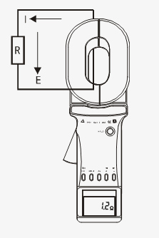
A2: The basic principle of the clamp ground resistance tester to measure the grounding resistance is to measure the loop resistance. The jaw part of the clamp meter consists of a voltage coil and a current coil. The voltage coil provides the excitation signal and induces a potential E on the loop under the test. Under the action of the potential E, a current I will be generated in the circuit under test. The clamp meter measures E and I, and the measured resistance R can be obtained by the following formula. The formula is R=E/I. This is how a clamp-on ground resistance tester works.
Q3: What is the earth resistance tester used for?
A3: The ground resistance tester can accurately measure the grounding impedance, grounding resistance and grounding reactance of large grounding grids.
- It accurately measures the surface potential gradient in the large-scale grounding grid area.
- Earth resistance tester can measure the contact potential difference, contact voltage, step potential difference and step voltage of large grounding grids.
- Measure the transfer potential of large-scale grounding grids and soil resistivity accurately.
- Digital earth resistance tester is used to measure the on-resistance of the grounding down-conductor.
Tips: Do you need to test soil resistivity regularly?
It depends on whether your current or future needs require soil resistivity testing as it will determine the type of ground resistance tester you need. For example, if your work involves the design or installation of a new grounding system, soil resistivity testing is a must. Many people use a ground resistance tester to test soil resistivity on a regular basis.
Thank you for buying industrial test and measurement equipment on SISCO.com, all products sold by SISCO and the partner cover a 12 months warranty, effective from the date of receiving the products.
What is covered?
SISCO is responsible for providing free spare parts, and free technical support to assist the customer to repair the defective products until the problem is solved.
What is not covered?
- Product purchased from anyone other than a SISCO store or a SISCO authorized reseller.
- Expendable parts.
- Routine cleaning or normal cosmetic and mechanical wear.
- Damage from misuse, abuse or neglect.
- Damage from use of parts other than SISCO approved.
- Damage from use outside the product’s usage or storage parameters.
- Damage from use of parts not sold by SISCO.
- Damage from modification or incorporation into other products.
- Damage from repair or replacement of warranted parts by a service provider other than a SISCO authorized service provider.
- Damage caused by the application environment not meeting the product usage requirements and the failure to perform preventive maintenance.

