
SISCO non-contact level switch delivers continuous liquid level monitoring with ±5mm accuracy and 1mm resolution. It features a configurable blind zone and adjustable integration time (0- 50 s) to adapt to various tank conditions. The measurement interval is approximately 1 second, providing timely updates. A digital display and push-button interface allow easy calibration and parameter adjustment, while the non-contact measurement principle ensures no wear on moving parts.
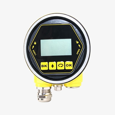
Reliable Measurement in Challenging Conditions
- Automatic temperature compensation adjusts the ultrasonic level switch in real time to minimize thermal drift, ensuring consistent ±5mm accuracy across the full 0-10m span.
- Narrow 26GHz beam angle concentrates acoustic energy, significantly reducing interference from internal obstructions and tank walls, which is critical for non-contact level switch installations.
- Blind zone management allows the non-contact level sensor to ignore the area near the antenna, preventing false echoes from affecting the measured value.
- Adjustable integration time (0–50s) enables the ultrasonic level sensors to smooth out rapid level fluctuations, providing a stable output without sacrificing response speed.
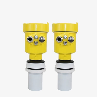
Flexible Signal Output and System Integration
- Simultaneous support for 4-20mA and HART protocols enables the non-contact ultrasonic liquid level sensor to interface with PLCs, DCS, and handheld communicators using the same two-wire loop.
- RS485/Modbus RTU digital output provides direct connection to SCADA networks, allowing multiple ultrasonic level switch units to be addressed on a single bus.
- Configurable fault indication allows the non-contact level sensor to output preset values (3.9mA, 20.5mA, or 22mA) to alert operators to a failure, improving system diagnostic capability.
- 1.6μA output resolution ensures that the ultrasonic level sensors transmit even small level changes as a proportional analog signal, facilitating high-precision external monitoring.
Applications
SISCO non-contact level switch is suitable for corrosive liquids, water treatment, chemical storage, and open channel flow monitoring. Its non-contact ultrasonic measurement ensures reliable performance in sticky, foaming, or agitated media. These ultrasonic level sensors also serve industrial tanks, sumps, and reservoirs requiring continuous level monitoring without contamination risk.

Chemical Industry

Food

Petroleum Industry

Water Treatment
| Model | SISCO-LS-043 |
| Measuring Range | 0–10 m |
| Accuracy | ±5 mm |
| Display Resolution | 1 mm |
| Operating Frequency | 26 GHz |
| Blind Zone | At antenna end |
| Output Signals | 4- 20 mA / HART (two-wire/four-wire), RS485/Modbus |
| Supply Voltage (two-wire standard) | 16–26V DC |
| Supply Voltage (two-wire IS) | 21.6–26.4V DC |
| Fault Signal | 3.9 mA / 20.5 mA / 22 mA (configurable) |
| Integration Time | 0–50 s (adjustable) |
| Measurement Interval | ~1 s |
| Process Connection | Thread or flange |
| Medium Temperature | –40 °C to +130 °C |
| Process Pressure | –0.1 to 0.3 MPa |
| Enclosure Rating | IP67 |
| Enclosure Window Material | Polycarbonate |
| Housing Seal | Silicone rubber |
| Cable Entry | M20×1.5 |
| Display | 2-inch LCD, 128×64 resolution |
| Storage Temperature | –20 °C to +70 °C |
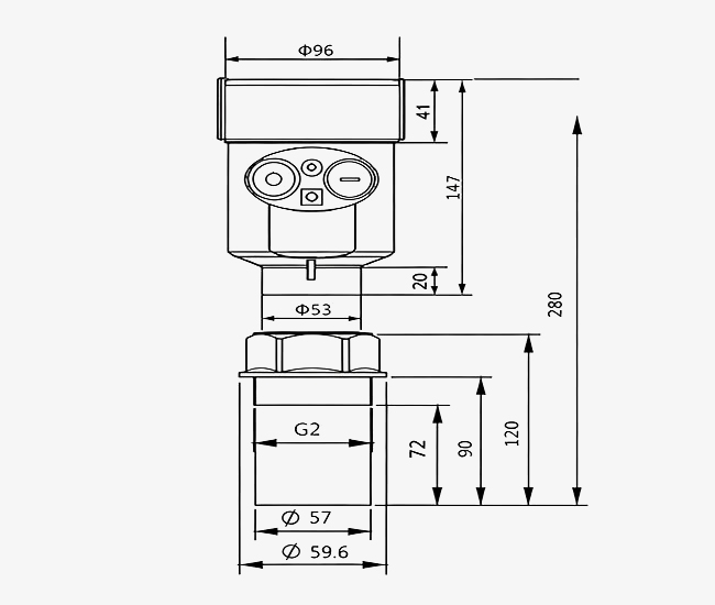
Dimensions (unit: mm)

Q1: What is the blind zone of this non-contact ultrasonic liquid level switch?
A1: The blind zone is located at the antenna end. For this non-contact level switch, the highest liquid level must remain below the antenna to ensure accurate measurement and avoid false echoes.
Q2: Which output signals does this ultrasonic level switch support?
A2: This ultrasonic level switch supports 4-20mA/HART (two-wire or four-wire) and RS485/Modbus. The non-contact level switch allows flexible integration with PLCs, SCADA, and handheld communicators.
Q3: What supply voltage is required for this non-contact level switch?
A3: The two-wire standard type requires 16–26V DC. For intrinsically safe installations, the ultrasonic level switch needs 21.6–26.4V DC. Please verify your power supply matches the ultrasonic level switch nameplate before wiring.
Tips: How to install and set up this non-contact ultrasonic liquid level switch?
- Verify the 4-20mA/HART loop integrity. Connect a multimeter in series to confirm the output current from the non-contact level switch corresponds to the actual measured level before connecting to the control system.
- Validate the blind zone setting. Ensure the highest liquid level remains below the antenna end of the ultrasonic level switch, as any material entering this zone will cause measurement errors.
- Confirm the installation position. The non-contact level switch should be mounted at 1/4 or 1/6 of the tank diameter, with a minimum distance of 200mm from the tank wall to avoid false reflections.
- Adjust the integration time parameter. Use the on-screen menu of this ultrasonic level switch to set the integration time between 0–50 seconds, smoothing out rapid level fluctuations for stable output.
- Record that the Ex ia IIC T6 Ga / Exd ia IIC T6 Gb housing is properly sealed. Verify all cover screws are tightened, and the M20×1.5 cable gland is securely fastened with the cable bent downward before energizing the system.
Thank you for buying industrial test and measurement equipment on SISCO.com, all products sold by SISCO and the partner cover a 12 months warranty, effective from the date of receiving the products.
What is covered?
SISCO is responsible for providing free spare parts, and free technical support to assist the customer to repair the defective products until the problem is solved.
What is not covered?
- Product purchased from anyone other than a SISCO store or a SISCO authorized reseller.
- Expendable parts.
- Routine cleaning or normal cosmetic and mechanical wear.
- Damage from misuse, abuse or neglect.
- Damage from use of parts other than SISCO approved.
- Damage from use outside the product’s usage or storage parameters.
- Damage from use of parts not sold by SISCO.
- Damage from modification or incorporation into other products.
- Damage from repair or replacement of warranted parts by a service provider other than a SISCO authorized service provider.
- Damage caused by the application environment not meeting the product usage requirements and the failure to perform preventive maintenance.

Shop on sisco.com for all of your industrial test and measurement equipment & accessories including portable detectors, meters, testers, scales, etc.


